PWM Tester Project
Purpose
At robotics, during the design phase, we prototype and test all different kinds of mechanisms to see which works best for this year’s game. I found that whenever we wanted to test a prototype, we would have to wire it into an existing robot control system and pass it to the programming team to write a small snippet of code to test the prototype. This process was slow and diverted work from other more important tasks, like building the drivetrain. I found that we needed an easier way to setup and test motorized prototypes.
Parts
- Mini OLED Display
- Arduino Trinket Pro
- Poteniometer and Knob
- Adafruit Lithium Polymer Battery
- Adafruit Lithium Charger Board
- Small On-Off Switch
- Prototyping Board
- Hammond Plastic Project Box
Details
To control the speed of a motor in our robot control system, we need to power the motor controller from a robot battery while giving a PWM signal to tell it how fast, and in what direction, to move the motor. PWM, or Pulse Width Modulation consists of a series of on-off pulses of electricity to form a square shaped wave. The width between pulses tells the motor controller how much voltage to give the motor, in turn varying the speed. 1000us, or microseconds, between pulses results in full speed reverse, 1500us is no movement (neutral), and 2000us is full speed forward.
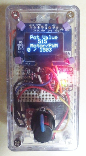
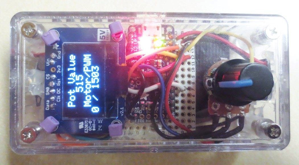
So, to generate a PWM signal for the motor controller, I setup a small Arduino microprocessor (an Adafruit Trinket) to be powered off a rechargeable battery. I programmed it to read the value of the potentiometer knob and output a PWM signal with the appropriate pulse width to vary the speed and direction at which the motor controller runs the motor.
More resources about this project can be found on my Github.