CNC Lathe Project
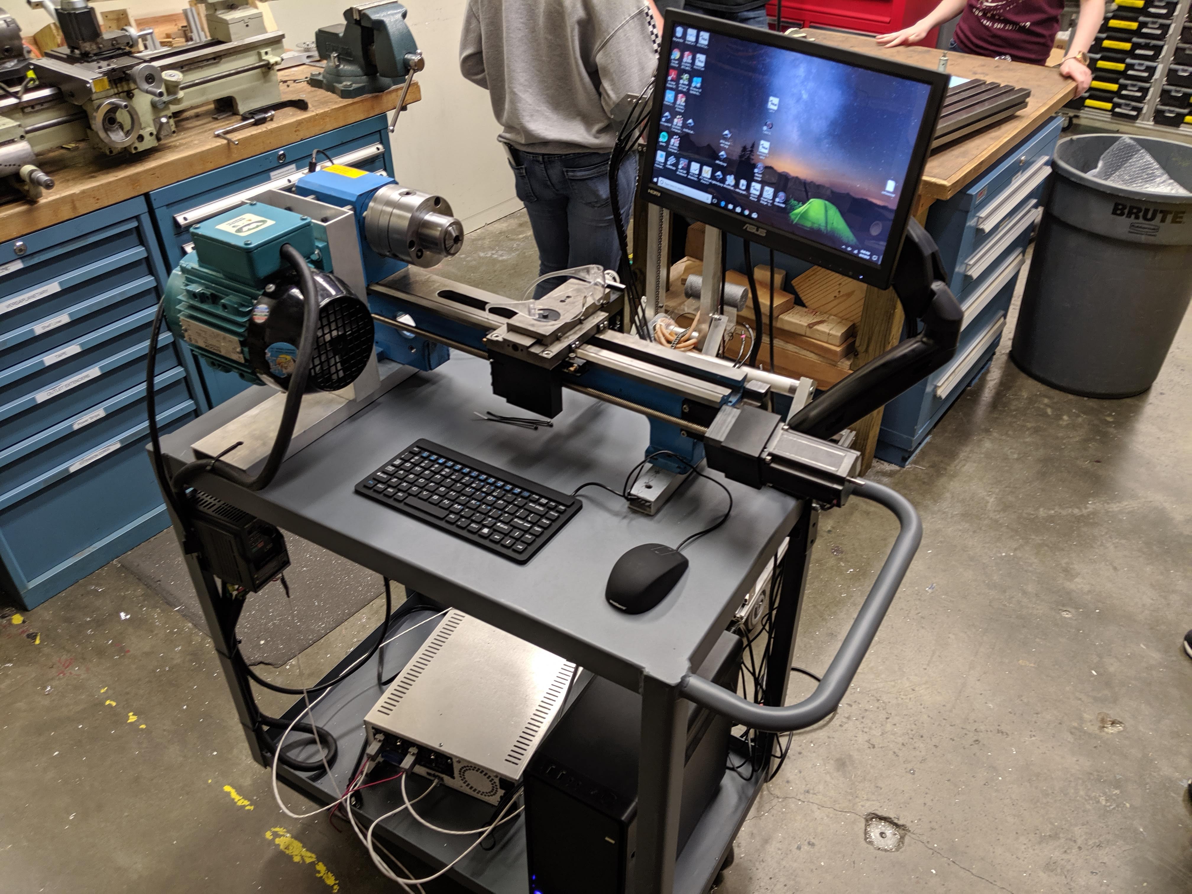
At robotics, one machine that gets used fairly often is our small lathe. Its main job is to make grooves in shafts for snap on retaining rings. Making these grooves manually takes time and labor. So, one of our mentors brought in a tiny, low cost lathe which had most of its parts taken from it. I am currently helping to convert this lathe into a computer controlled lathe which can automatically create snap ring grooves with greater accuracy, faster and with less work.

Parts
- Small Low Cost Manual Lathe
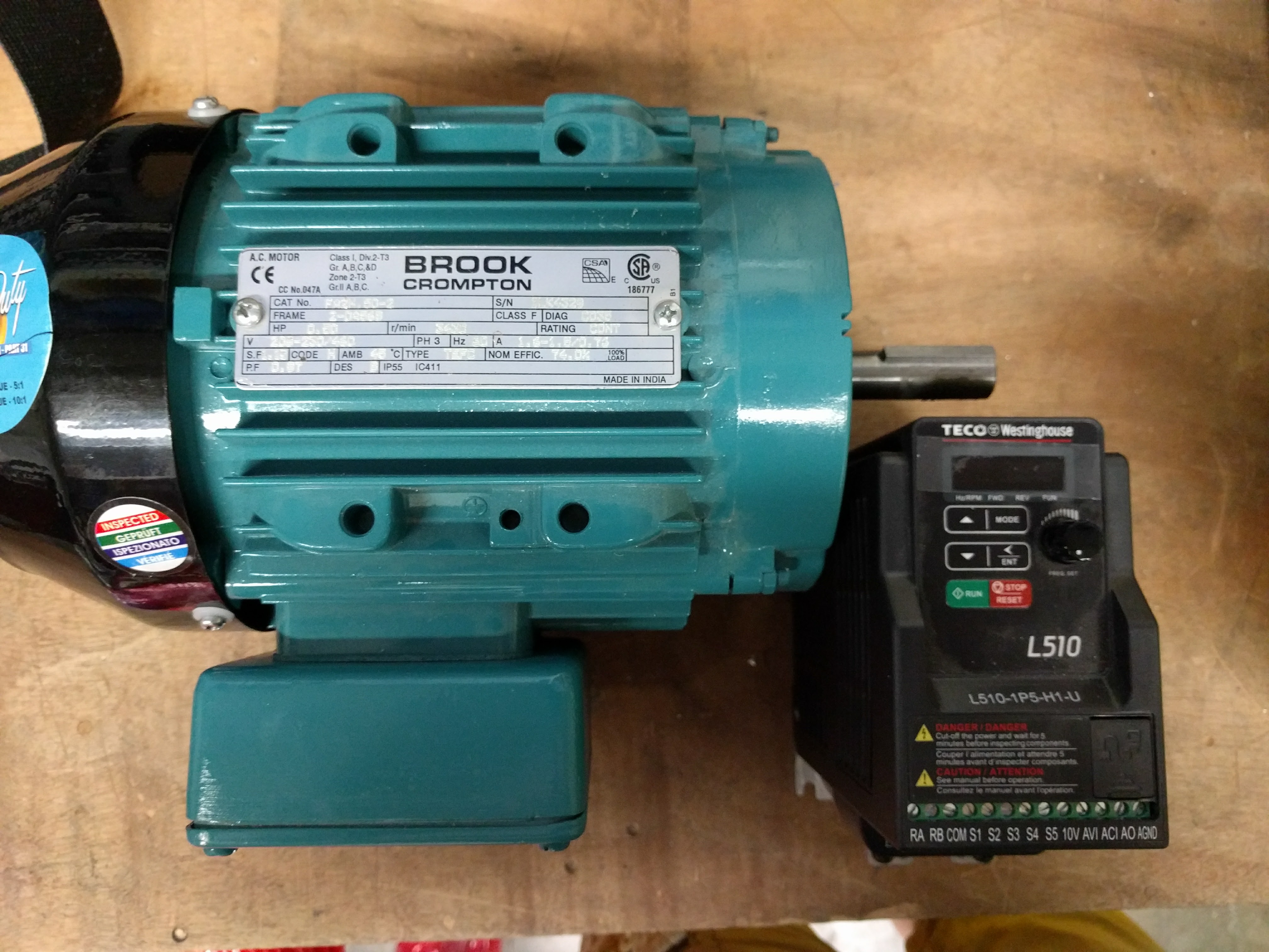
- Large 1/2 Horsepower 3 Phase Motor
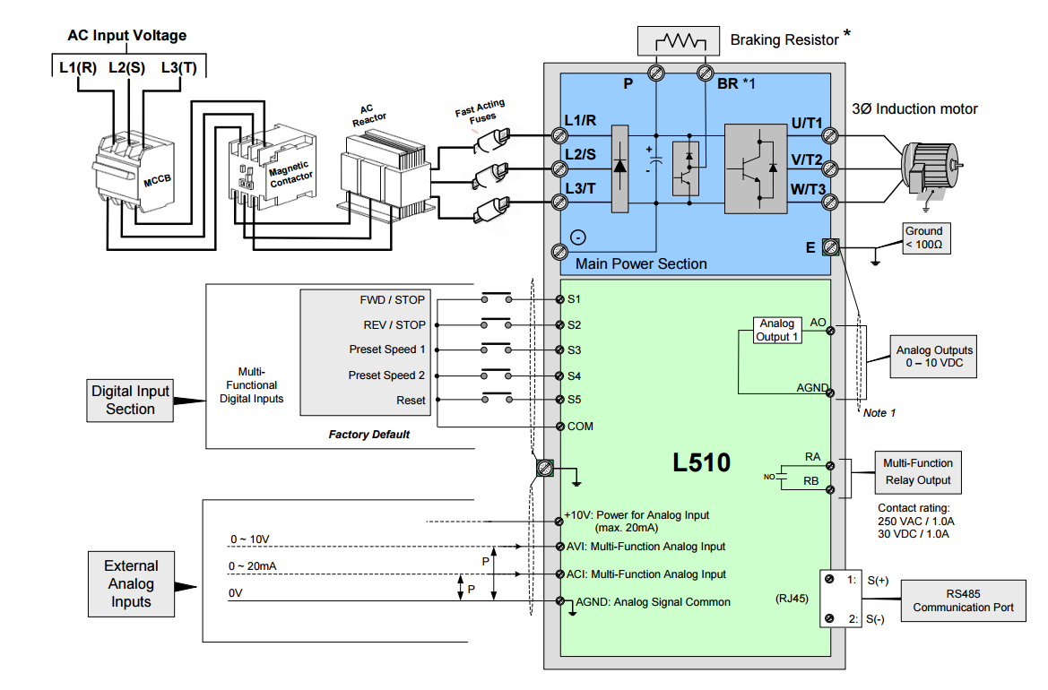
- Three Phase Variable Frequency Drive
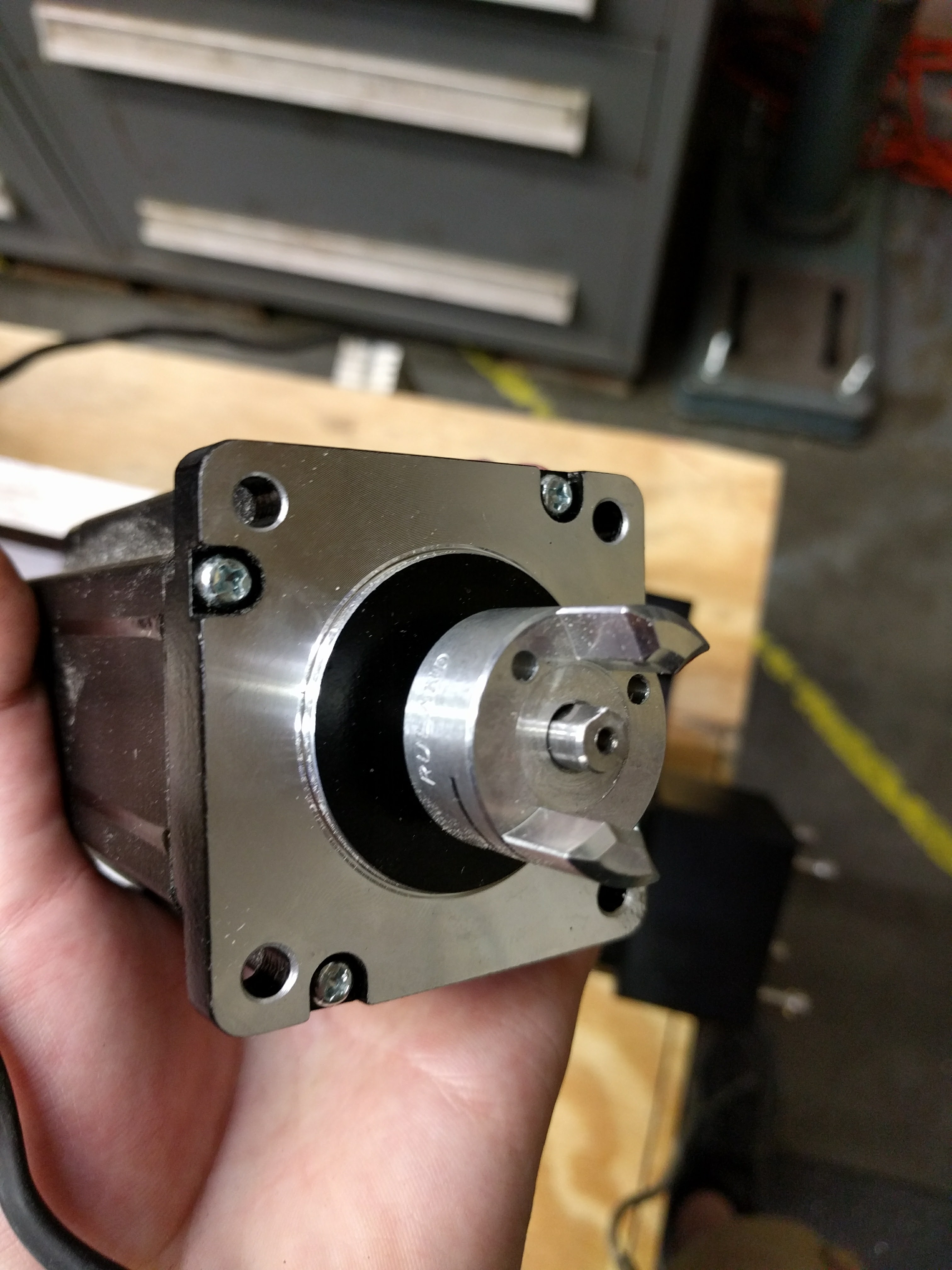
- High Torque Stepper Motors
- Stepper Motor Drivers
- Rotary Encoder for Sensing Speed
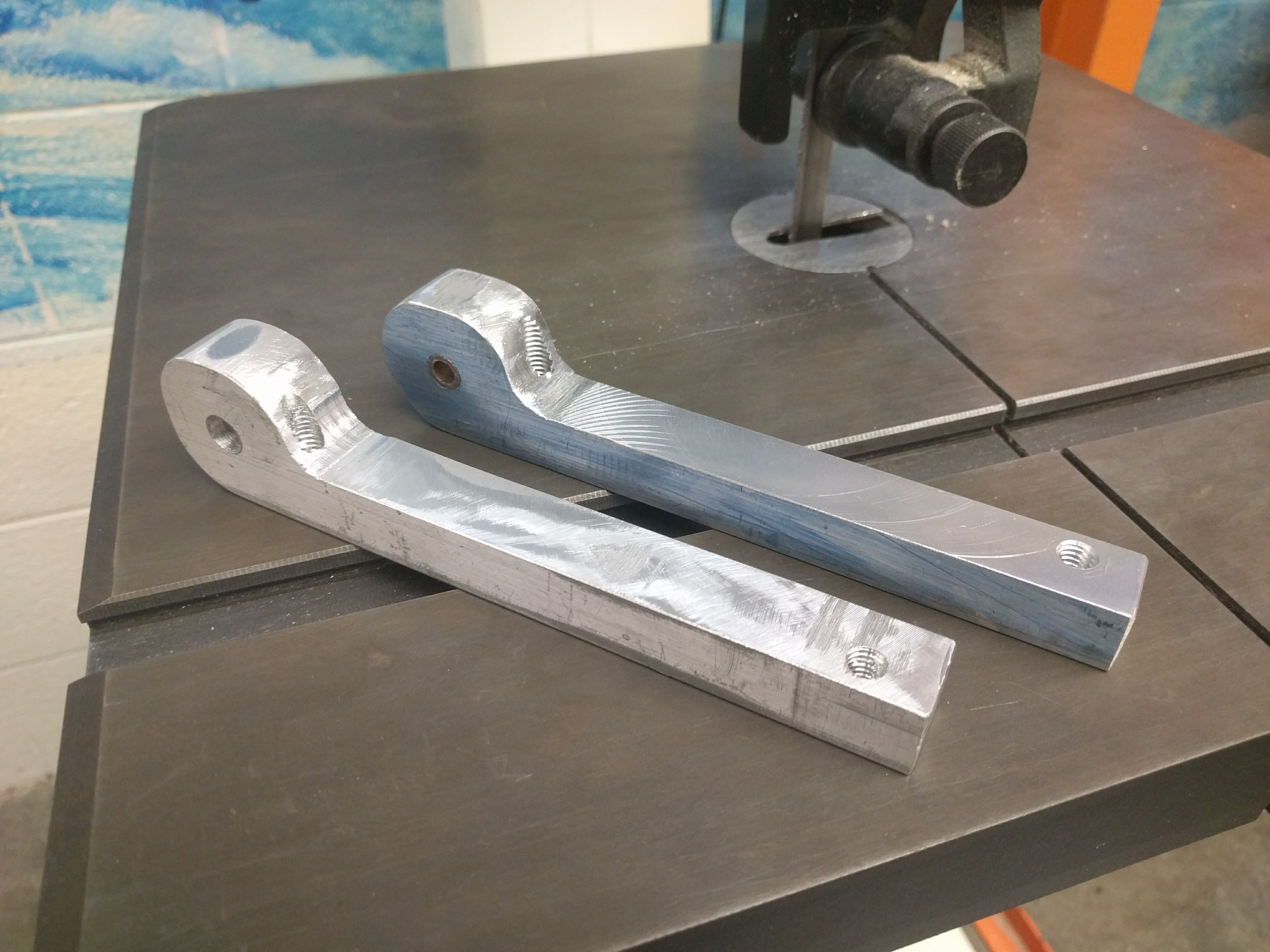
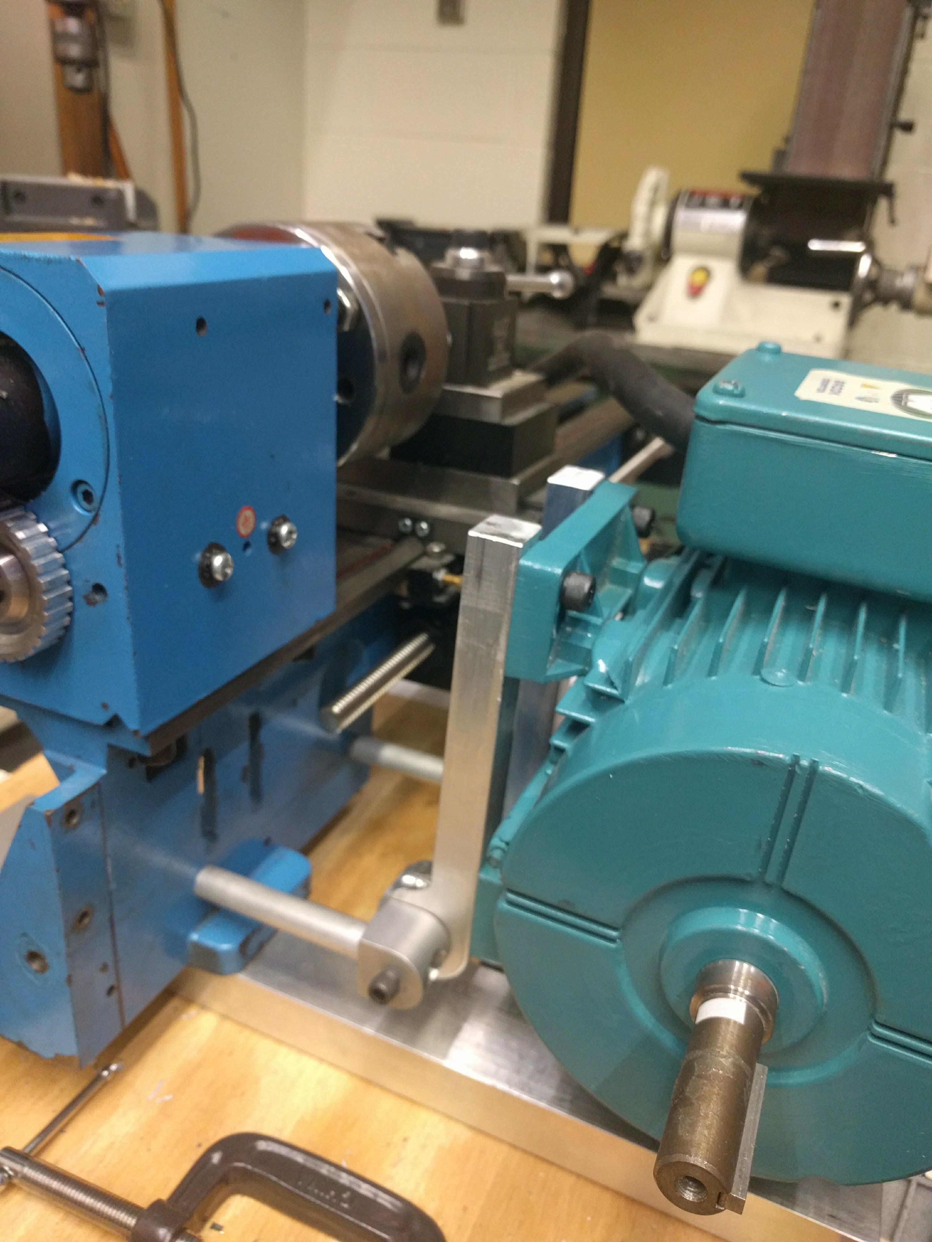
We started by stripping the lathe down to its bare mechanical components. I, then, designed and machined motor mounting brackets to support a much larger and more powerful motor upgrade. This new motor was a 240 Volt, 3 Phase induction motor, which meant it didn’t run off normal wall outlet power. We needed a VFD, or Variable Frequency Drive, to convert the single phase power from a wall outlet to 3 phase power to run the motor. A huge benefit of using a VFD is that you can program it to have many inputs and outputs, to control the motor from software or sensors. VFD also provides speed and torque control, and can regulate current draw and temperature.